The world is digital nowadays, and most information is represented in numbers. However, human nature is more "analog" and is better represented the old-fashion way, using pointer gauges and bar graphs.
Pointer gauges can be found in various industrial applications. Automobiles, trains, and even modern aircraft dashboards emulate analog gauge functionality on flat panel plasma controls or TFT screens. It looks like good old pointer gauges won’t be disappearing soon.
Various techniques can be used to control pointer gauges. The most popular technique is to use a mechanical system, which consists of a turning coil mounted outside a two-pole permanent magnet. The applied DC current causes a magnetic force that rotates the coil and associated gauge pointer. Springs limit the coil rotation angle and the stable pointer rotation angle is in direct proportion to the coil current. Such a gauge can be equipped with an oil damper to suppress oscillations during coil angle setup and improve the system’s mechanical stability with respect to vibration. This method has limitations in the operational temperature range because oil viscosity changes with temperature, causing the gauge to be unstable amid vibrations.
Other gauges use a bimetallic plate with a heater. This type consumes considerable current during operation and readings are dependent on environmental temperature.
An alternative approach uses two quadrature-located coils to set the pointer position. In this system, the pointer rotation angle is determined in relation to the coil currents. A mechanical damper is still required to prevent pointer flicker due to mechanical vibrations at setup time.
A perfect way to control a pointer gauge is to use a small stepper motor specially designed for pointer control. Today, many companies provide stepper motors for gauges. Brands include Siemens, Sonceboz, Switec, RY etc.
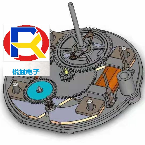
These motors are characterized by small size (about 1” in diameter, 0.3” in height), low power, and favorable cost, can be driven directly by the microcontroller due to low operation current (15-25mA per coil). Gauge motors have built-in gearboxes, which increase motor torque and reduce the mechanical step, providing smooth pointer rotation for large pointers. Next figure shows photos and internal construction elements of motors from several different companies.

As can easily be seen from this photo, the motor consists of two coils, a metal stator, a small permanent magnet rotor and plastic gearbox. Some motors have internal stop, which limits the pointer potation angle; others use external stop. Motors from different vendors have different stator construction, rotor diameters and gearbox ratios.
Motor driving principles
The gauge motors are stepper motors which operate in microstep mode. These motors need two phase-shifted analog signals. Many motors are driven by quadrature, 90*-phase-shifted harmonic signals, but alternative phase shift values (60*, 101*, etc) and non-harmonic waveforms are encountered as well. These signals can be formed by double PWM or DAC using lookup tables.
However, we should determine the driving speed profiles as well. There are several possible strategies for motor speed control, using either constant or variable speed operation. The motor datasheet provides several useful graphs for starting and operating torque vs. control-signal frequency (see example on Figure 2). As can be seen easily from these graphs, the maximum start-up frequency is much less than the maximum operation frequency. Therefore, the constant speed profile does not provide minimum pointer setup time. The variable speed driving profile is free from this limitation, allowing the use of all available motor capabilities and the attainment of minimal pointer setup time.
The stepper motor is a synchronous electric machine and the angle of the rotor can be uniquely determined by the relation of phase currents. Due to the inherent limitation in the coil driving force, the acceleration/deceleration value should be limited to avoid causing the indicator to skip a step.
In the stepper motor gauge design, it is possible to select different motor acceleration and deceleration schemes.
One scheme can use a constant acceleration profile. This type of profile is useful when the rotation speed is increased at constant acceleration during the acceleration phase, with a corresponding deceleration during the deceleration phase. The rotational speed is constant when the speed reaches a predefined threshold. This driving profile is sometimes called a trapezoidal profile, since the speed profile assumes the shape of a trapezoid. This profile assures minimum pointer setup time.
Another possible solution uses a digital compensator to gradually increase the rotational speed during the motor acceleration phase and to smoothly decrease the speed during the deceleration phase. When this scheme is used, the absolute value of the acceleration must also be within the allowed bounds of the motor. You can obtain more information about stepper motor control from
AN2229 “Multi-Functional Stepping Motor Driver” Application Note.
This driver can be implemented with a microcontroller and some application requirements. The following modules are necessary:
· A double-PWM or DAC to form the coil currents;
· A variable frequency generator to generate the updating events for the coils’ current values to determine the rotational speed;
· A speed control subsystem to provide rotational acceleration and deceleration stages.
Modern microcontrollers have PWMs and some have build in DACs to allow formation of variable coil current. The programmable interval timer can be used as a variable frequency generator for rotation speed control. However, the change in linear motor rotation speed corresponds to a hyperbolic timer period curve, which requires a higher-resolution timer.
PSoC provides an alternative solution due to its flexible internal analog user modules. The voltage-to-frequency converter (V/F), coupled with DAC, creates a programmable, variable frequency signal generator with a constant frequency step. This is the method is used in this
Application Note. The released digital blocks can be used for other purposes, running the communication interface for example or as PWM sources.
In some applications, gauges are used as standalone devices, handling analog or digital input signals directly. Other applications require networked gauges, which are controlled by a central processor using a chosen bus (CAN, LIN, J1587, and others)


